For week 3, it was an important step. We made efforts to soldered the shield kit which can make the motor work. However, there were some troubles with Raspberry Pi witch made us give it up. The system of Raspberry was installed successfully, but we could hardly get through how it controls the car. Still, only with Arduino the project can work the same well.
Achievements
- The shield was received and soldered successfully.
- The codes were able to run.
- Installed the system of Raspberry Pi.
Problems
- There were difficulties to use Raspberry Pi.
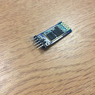
- The Bluetooth mode could not work well on the car.
- The Battery case has much too high voltage (12 V).
The picture of the shield kit
Figure 1. The Instruction of the Shield (from online)
Figure 2. The Actual Image of Our Shield
It was a kit when received including all the parts including resistors, capacitors, switches and so on. As you can see, it was soldered perfectly and could work well with power connected. For the connection, the output A and B are connected to the motors while the power is connected to the batteries.
The IC on the shield -- The L298
Below are the pin connection introduction and the circuit of bidirectional DC motor control.
Figure 2. The Pin Connection of the L298 [1]
Figure 3. The Bidirectional DC Motor Control Circuit[1]
Comments
The car was able to move, but not worked well with voice control. It didn't work well with Raspberry Pi 3. The connection of pins and wires can be wrong. Codes need further debug.
Reference
- https://www.sparkfun.com/datasheets/Robotics/L298_H_Bridge.pdf


